Structured Cabling Best Practices: Mitigating EMI and RFI in UK Smart Home Installations
As a UK-certified installer, my name is Gary Pearce, and I've witnessed firsthand the transformative power of smart home technology. From intelligent lighting and climate control to integrated security and entertainment systems, modern homes in the UK are becoming increasingly interconnected. This evolution, while incredibly beneficial, brings with it a critical underlying challenge: ensuring the reliability and performance of the vast network infrastructure that supports these systems. The silent saboteurs of this intricate web are Electromagnetic Interference (EMI) and Radio Frequency Interference (RFI).
In this detailed technical guide, I will delve into the best practices for structured cabling, specifically engineered to mitigate EMI and RFI, ensuring that your UK smart home installation operates flawlessly and stands the test of time. My aim is to provide an engineering-grade perspective, offering practical, actionable insights for installers and discerning homeowners alike.
Understanding EMI and RFI: The Invisible Threats
Before we can effectively mitigate EMI and RFI, it's imperative to understand what they are, their sources, and their detrimental effects on data networks.
Electromagnetic Interference (EMI) refers to any unwanted electrical or electromagnetic energy that degrades the performance of electronic equipment. It can manifest as conducted interference (travelling through power lines or data cables) or radiated interference (travelling through the air as electromagnetic waves).
Radio Frequency Interference (RFI) is a subset of EMI, specifically referring to interference in the radio frequency spectrum. While all RFI is EMI, not all EMI is RFI. RFI is typically associated with high-frequency signals that can disrupt wireless communication and high-speed data transmission over wired connections.
Common Sources of EMI/RFI in a UK Smart Home Environment:
The modern home is a hotbed of potential interference sources. Categorising them helps in developing targeted mitigation strategies:
Internal Sources (within the property):
- Power Distribution: Mains wiring (230V AC), electrical panels, dimmer switches (especially older resistive or inductive types), switched-mode power supplies (SMPS) common in consumer electronics and LED drivers.
- Appliances: Induction hobs, microwave ovens, washing machines, refrigerators, vacuum cleaners, and other devices with motors or complex electronics.
- HVAC Systems: Electric motors in air conditioning units, heat pumps, and ventilation fans.
- Lighting: Fluorescent lights, compact fluorescent lamps (CFLs), and LED lighting (especially low-quality drivers).
- Data Equipment: Wi-Fi routers, cordless phones, Bluetooth devices, and even poorly shielded data cables themselves (producing crosstalk).
- Security Systems: Certain sensors or camera power supplies.
External Sources (outside the property):
- Broadcast Transmitters: Local radio and television transmitters.
- Mobile Phone Masts: Transmitting signals in various frequency bands.
- Industrial Equipment: Nearby factories, machinery, or heavy electrical plant.
- Transportation: Car ignition systems, electric vehicle charging points.
- Power Lines: Overhead power lines, especially high-voltage ones.
The Impact of EMI/RFI on Smart Home Performance:
The consequences of unchecked EMI/RFI can range from frustratingly intermittent issues to complete system failure:
- Data Corruption: Errors in transmitted data packets, requiring retransmission, slowing down the network.
- Reduced Bandwidth & Throughput: Interference can limit the effective data rate, making high-bandwidth applications (e.g., 4K/8K video streaming, online gaming) sluggish or unworkable.
- Intermittent Connectivity: Devices frequently drop offline or lose connection.
- Increased Latency: Delays in communication, particularly noticeable in real-time applications like video conferencing or smart home automation command execution.
- Device Malfunction: Smart devices behaving erratically or failing to respond to commands.
- Security Vulnerabilities: In severe cases, data integrity issues can compromise security protocols.
The Indispensable Role of Structured Cabling
While Wi-Fi offers convenience, a robust structured cabling system is the bedrock of a truly reliable and high-performance smart home. For critical applications, wired connections offer unparalleled stability, speed, and security. Think of it as the nervous system of your smart home, delivering consistent data streams where wireless signals might falter due to distance, obstacles, or, crucially, EMI/RFI.
Why Wired is Superior for Critical Smart Home Applications:
- Guaranteed Bandwidth: Dedicated connections eliminate contention and provide consistent data rates essential for streaming high-resolution content (e.g., multiple 4K/8K feeds), online gaming, and large file transfers.
- Lower Latency: Direct paths result in quicker response times, vital for instantaneous smart home automation and critical security systems.
- Enhanced Security: Wired connections are inherently more difficult to intercept or jam compared to wireless signals.
- Power over Ethernet (PoE): The ability to power devices like IP cameras, access points, smart lighting, and touch panels directly over the data cable, simplifying installation and reducing clutter.
- Future-Proofing: A well-designed structured cabling system (e.g., Cat6a or higher) can support network speeds far exceeding current Wi-Fi standards and provides a stable platform for future technologies.
Adherence to Standards: The Foundation of Quality
In the UK, structured cabling installations must comply with relevant British and European standards to ensure interoperability, performance, and safety. Key standards include:
- BS EN 50173 Series: Information technology. Generic cabling systems. This is the cornerstone for UK cabling, specifying requirements for various cabling types (copper, fibre) and environments (residential, commercial).
- BS EN 50174 Series: Information technology. Cabling installation. This series details installation planning and practices.
- BS 7671 (IET Wiring Regulations): Although primarily for electrical installations, it is crucial for safe cable routing, segregation from power, and earthing/bonding.
- TIA-568 Series: While a North American standard, its principles for category cabling (Cat5e, Cat6, Cat6a, etc.) are globally recognised and adopted.
As a certified installer, strict adherence to these standards is not merely a recommendation; it is a professional obligation and a guarantee of quality.
Key Mitigation Strategies: The Design Phase
Effective EMI/RFI mitigation begins long before the first cable is laid. It's an integral part of the design phase, requiring careful consideration of cable types, routing, and grounding.
1. Cable Selection: The First Line of Defence
The choice of data cable is paramount. The primary distinction for EMI/RFI mitigation lies between unshielded and shielded twisted pair cables.
- Unshielded Twisted Pair (UTP):
- Construction: Pairs of copper wires twisted together, without any metallic shielding.
- EMI/RFI Mitigation: Relies entirely on the twisting of pairs to cancel out external electromagnetic noise (common-mode rejection) and internal crosstalk. The tighter the twist, the better the performance (e.g., Cat6 has tighter twists than Cat5e).
- Pros: Lower cost, easier to install, smaller diameter, no grounding requirements.
- Cons: Less effective against external EMI/RFI, more susceptible to alien crosstalk (AXT) in bundles (especially Cat6a and higher).
- Typical Applications: General office environments, short runs in low-noise residential settings.
- Shielded Twisted Pair (STP) / Foiled Twisted Pair (FTP) Variants:
- Construction: These cables incorporate metallic shielding (foil, braid, or both) around individual pairs or the entire cable bundle, in addition to the twisted pairs.
- EMI/RFI Mitigation: The shield acts as a Faraday cage, reflecting or absorbing external electromagnetic energy and preventing it from reaching the data-carrying conductors. It also contains internally generated EMI, reducing emissions. Effective shielding requires proper grounding.
- Pros: Superior EMI/RFI immunity, improved alien crosstalk performance, better signal integrity over longer distances.
- Cons: Higher cost, larger diameter, more rigid, requires proper grounding/bonding for effectiveness, more complex termination.
- Types:
- F/UTP (Foiled/Unshielded Twisted Pair): An overall foil shield around all unshielded pairs. Offers good protection against external EMI.
- U/FTP (Unshielded/Foiled Twisted Pair): Individual foil shields around each pair, but no overall shield. Excellent for reducing alien crosstalk and internal noise.
- S/FTP (Shielded/Foiled Twisted Pair): An overall braided shield around individually foiled pairs. Offers the highest level of protection against both external EMI/RFI and internal alien crosstalk. Often referred to as "PiMF" (Pairs in Metal Foil).
Technical Comparison: Cable Categories and Shielding
| Cable Category | Max Bandwidth (MHz) | Max Speed (Gbps) | Shielding Options | Primary Use Case (Smart Home) | EMI/RFI Mitigation Level | Notes (UK context) |
|---|---|---|---|---|---|---|
| Cat5e | 100 | 1 | UTP | Basic IP devices | Low | Largely obsolete for new smart home installations. |
| Cat6 | 250 | 1 | UTP, F/UTP | General IP connectivity | Medium | Suitable for many current uses, but limited for future. |
| Cat6a | 500 | 10 | UTP, F/UTP, S/FTP | High-speed backbones, 4K/8K media, PoE++, Wi-Fi 6E APs | High | Recommended minimum for new builds, good future-proofing. |
| Cat7 / Cat7a | 600 / 1000 | 10 | S/FTP (PiMF) | Ultra-high performance, professional AV | Very High | Less common in residential; specific component requirements. |
| Cat8 | 2000 | 25 / 40 | S/FTP (PiMF) | Data Centres, future extreme bandwidth | Extreme | Overkill for most current smart homes, but ultimate future-proof. |
LSZH (Low Smoke Zero Halogen) Considerations:
In the UK, especially for installations in public access areas or larger residential properties, specifying LSZH jacketed cables is crucial. These cables emit minimal smoke and no toxic halogens when exposed to fire, significantly improving safety in an emergency. This is often a building regulation requirement, not just a recommendation.
2. Route Planning and Segregation: The Path to Purity
The physical routing of data cables is just as critical as the cable type. The principle here is simple: keep data cables as far away as possible from sources of EMI/RFI.
- Separation from Power Cables: This is arguably the most critical design rule. Data cables should never run parallel to power cables for extended distances.
- BS EN 50174-2 guidelines (derived from IEC 60364-5-52) recommend minimum separation distances:
- No separation required: If data cables are in earthed metallic conduit or metallic trunking, or shielded power cables are used.
- 50mm: For data cables in plastic conduit/trunking crossing typical power cables.
- 100mm: For data cables in plastic conduit/trunking running parallel to typical power cables for lengths up to 35m.
- >150mm: For longer parallel runs, or when running near high-power circuits (e.g., induction hobs, HVAC units, solar PV cabling).
- Crossing Power Cables: When data and power cables must cross, they should do so at a 90-degree angle. This minimises the coupling of electromagnetic fields.
- Dedicated Pathways: Utilise separate conduits, trunking, or cable trays for data cables and power cables. If sharing a multi-compartment trunking system, ensure there is a solid metallic barrier between compartments.
- Avoidance of Known Noise Sources: Plan routes to bypass areas with high electromagnetic fields, such as near electric motors, transformers, fluorescent light ballasts, dimmer switches, and large appliances.
- Grounding Electrode System: Ensure a robust, compliant grounding electrode system (main earthing terminal) as per BS 7671.
3. Grounding and Bonding: The Shield's Backbone
For shielded cabling systems (F/UTP, S/FTP), proper grounding and bonding are non-negotiable. Without an effective earth connection, the shield acts as an antenna, potentially attracting noise rather than mitigating it.
- Single-Point Grounding: For optimal performance, especially in shielded systems, the shield should be bonded to earth at only one end, typically at the patch panel in the telecommunications room (TR). This prevents ground loops, which can introduce noise. However, in environments with significant external EMI, it might be necessary to bond both ends if an equipotential bonding network is present to prevent ground loops. Generally, for residential, single-point is preferred unless specifically engineered otherwise.
- Equipotential Bonding: All metallic components of the structured cabling system (racks, patch panels, conduits, trunking) must be bonded together and connected to the main earthing terminal (MET) of the electrical installation. This ensures that all components are at the same electrical potential, preventing hazardous voltage differences and minimising noise.
- Step-by-Step Guide: Proper Grounding of Shielded Cables (at the patch panel)
1. Select Shielded Components: Use shielded patch panels and shielded keystone jacks.
2. Cable Preparation: Strip the cable jacket carefully, exposing the overall foil or braid shield and the drain wire.
3. Ensure Shield Contact: For punch-down blocks or keystone jacks, ensure the drain wire or shield makes continuous contact with the metallic housing of the connector. Some patch panels have dedicated grounding bars or points for the drain wires.
4. Terminate Drain Wire: Securely attach the drain wire to the designated grounding point on the shielded keystone jack or patch panel. For some S/FTP cables, the overall braid connects directly.
5. Bond Patch Panel to Rack: Ensure the shielded patch panel is securely mounted into an earthed equipment rack or enclosure. The rack itself must be bonded to the MET.
6. Outlet Grounding: At the wall outlet, the shielded keystone jack should make contact with an earthed faceplate, or its metallic housing should be bonded to the local earth. However, the shield continuity itself should ideally be maintained through the cable to the single ground point at the patch panel. The critical thing is continuity of the shield along the cable and its components, terminating at the designated ground.
Key Mitigation Strategies: The Installation Phase
Even the best design can be undermined by poor installation practices. Meticulous execution is crucial.
1. Proper Termination Techniques: The Devil is in the Detail
- Maintaining Twist Rates: The twists in twisted pair cables are fundamental to their performance. When terminating, minimise the untwisting of pairs to the absolute minimum required by the connector type (typically no more than 13mm or 0.5 inches). Excessive untwisting drastically degrades crosstalk performance and EMI immunity.
- Shield Continuity (for Shielded Cables): For shielded cables, the shield must be continuous from end to end and properly terminated at the grounding point. Any breaks in the shield or poor contact at connectors will render the shielding ineffective. Use shielded RJ45 connectors (e.g., Cat6a STP RJ45) with metal housings that make contact with the cable shield.
- Bend Radius: Cables have a minimum bend radius (typically 4 times the cable diameter for horizontal cables). Exceeding this can damage the internal conductor insulation, alter the cable's electrical properties (impedance), and compromise twist rates, leading to performance degradation and increased susceptibility to EMI/RFI. For Cat6a, this might be around 25-30mm.
- Pulling Tension: Do not exceed the cable manufacturer's maximum pulling tension (e.g., 110 Newtons for Cat6a). Excessive pulling tension can stretch the conductors, alter twist rates, and damage the insulation, affecting cable performance and data integrity. Use appropriate pulling lubricants and grips.
2. Patch Panels and Outlets: System Integrity
- Matching Components: Always use components (patch panels, keystone jacks, patch leads) that match or exceed the category rating and shielding type of the installed cable. Using a UTP patch panel with S/FTP cable will negate the benefits of the shielding.
- High-Quality Components: Invest in quality components from reputable manufacturers. Cheap, uncertified components often have poor internal construction, leading to reduced performance and increased susceptibility to noise.
3. Power over Ethernet (PoE) Considerations: The Heat Factor
PoE (802.3af, 802.3at, 802.3bt) introduces additional considerations for EMI/RFI mitigation, primarily due to heat generation.
- Heat Generation: When power is transmitted over multiple pairs within a cable, especially in large bundles, resistive heating occurs. This heat can degrade cable performance, particularly insertion loss.
- Bundle Size and Fill Ratio: Carefully manage cable bundle sizes. Follow recommendations for pathway fill ratios to allow for adequate airflow and heat dissipation. Over-stuffing conduits or trays can lead to excessive heat build-up.
- Cable Type for High PoE: For high-power PoE (PoE++ / 802.3bt Type 3 and 4), consider cables specifically designed for higher temperature ratings or those with larger conductor gauges (e.g., 23 AWG for Cat6a is better than 24 AWG for heat dissipation).
- Separation from Heat Sources: Ensure PoE cabling is not routed near other heat-generating equipment.
Testing and Validation: Proving Performance
Upon completion of installation, comprehensive testing is non-negotiable. This validates that the system meets performance specifications and that EMI/RFI mitigation strategies have been effective.
1. Certification Testing: The Gold Standard
- Certified Testers: Use industry-standard cable certifiers (e.g., Fluke Networks Versiv series) for full channel or permanent link certification. These devices perform a battery of tests to ensure compliance with TIA/ISO/EN standards.
- Key Parameters to Test:
- Wire Map: Confirms correct termination (no opens, shorts, or split pairs).
- Length: Verifies cable length within specifications.
- Insertion Loss (Attenuation): Measures signal loss over the cable.
- Return Loss: Measures reflections caused by impedance mismatches.
- Near-End Crosstalk (NEXT) & Power Sum NEXT (PSNEXT): Measures interference between pairs within the same cable at the near end.
- Far-End Crosstalk (FEXT) & Power Sum FEXT (PSFEXT): Measures interference between pairs within the same cable at the far end.
- Attenuation-to-Crosstalk Ratio (ACR-N) & Power Sum ACR-N (PSACR-N): Combines insertion loss and crosstalk to provide a signal-to-noise ratio.
- Equal Level Far-End Crosstalk (ELFEXT) & Power Sum ELFEXT (PSELFEXT): Measures alien crosstalk performance.
- Propagation Delay & Delay Skew: Measures signal travel time and the difference in travel time between pairs.
- Alien Crosstalk (AXT): Crucial for Cat6a and higher, this measures interference from adjacent cables in a bundle. Certifiers can test for PSANEXT (Power Sum Alien Near-End Crosstalk) and PSAACRF (Power Sum Alien Attenuation to Crosstalk Ratio Far-End).
- Documentation: Generate and provide detailed test reports to the client, forming part of the handover documentation. This provides tangible proof of quality and can be invaluable for future troubleshooting.
2. Troubleshooting Common EMI/RFI Issues:
- Visual Inspection: Re-check all terminations for proper untwist, shield continuity, and bend radius violations.
- Grounding Audit: Verify all grounding connections for shielded systems. Use a multimeter to check continuity from the shield to the ground point.
- Environment Scan: Use a spectrum analyser to identify high-intensity EMI/RFI sources in the environment that might be impacting the cabling. This can help pinpoint external culprits.
- Component Isolation: If an issue is suspected in a specific part of the network, systematically replace components (patch leads, keystone jacks, patch panels) with known good ones to isolate the fault.
Maintaining Performance Post-Installation
A professionally installed structured cabling system is built for longevity, but its performance can be compromised by subsequent modifications or negligence.
- Avoid Unqualified Modifications: Educate homeowners against modifying the cabling system themselves or allowing unqualified personnel to do so. Simple mistakes like using unshielded patch leads with a shielded system, or overtightening cable ties, can degrade performance.
- Environmental Factors: Protect exposed cabling from physical damage, extreme temperatures, and moisture.
- Future Expansion: When planning future smart home additions, consult with a qualified installer to ensure any new cabling integrates seamlessly and adheres to existing best practices for EMI/RFI mitigation.
Conclusion
The promise of a truly intelligent smart home in the UK relies heavily on an unseen hero: the structured cabling system. EMI and RFI represent significant, yet often overlooked, threats to this foundation. By adopting an engineering-grade approach from the design phase through to installation and validation, utilising shielded cabling where appropriate, meticulously planning routes, ensuring robust grounding, and adhering to industry standards, we can effectively mitigate these interferences.
As a UK-certified installer, I advocate for these best practices not just for optimal performance today, but for the future-proofing and long-term reliability of your smart home investment. Don't compromise on the hidden infrastructure; it's the lifeline of your connected world. For professional guidance or to discuss your specific smart home cabling requirements, please use the online contact page to get in touch.
Frequently Asked Questions (FAQ)
Q1: Why can't I just use Wi-Fi for everything in my smart home?
While Wi-Fi offers unparalleled convenience, it inherently suffers from limitations that wired structured cabling overcomes, especially in a dense smart home environment. Wi-Fi bandwidth is shared among all connected devices, making it susceptible to congestion, interference from other wireless devices (both inside and outside your home), and signal degradation over distance and through walls. Wired connections provide dedicated, guaranteed bandwidth, lower latency, superior security, and immunity to electromagnetic interference, making them essential for high-priority applications like 4K/8K video streaming, online gaming, IP security cameras, and critical smart home automation controllers. For a truly robust and reliable smart home, a hybrid approach leveraging the strengths of both wired and wireless is ideal.
Q2: What is the single most critical aspect of mitigating EMI/RFI in structured cabling?
While all aspects are important, the most critical aspect for mitigating EMI/RFI, particularly in shielded systems, is proper grounding and bonding. A shielded cable, without an effective and continuous path to earth, can act as an antenna, attracting noise rather than dissipating it. Conversely, proper grounding ensures the metallic shield reflects or absorbs interference, safely directing it away from the data-carrying conductors. Coupled with appropriate cable segregation from power sources, this forms the cornerstone of effective EMI/RFI defence.
Q3: Is Cat6a sufficient for most UK smart home installations, or should I consider Cat7/8?
For the vast majority of UK smart home installations, Cat6a (Category 6 Augmented) is the recommended minimum and often sufficient cable type. It reliably supports 10 Gigabit Ethernet (10GBASE-T) over distances up to 100 metres, which is more than adequate for current and foreseeable smart home demands, including multiple 4K/8K video streams, high-speed internet access, and advanced PoE applications. While Cat7/7a and Cat8 offer even higher bandwidth (up to 10 Gbps and 40 Gbps respectively), they come with significantly increased cost, complexity in termination, and require a full end-to-end shielded system. The performance benefits of Cat7/8 are largely realised in data centre environments, and their full potential is rarely leveraged in a typical residential setting, making Cat6a the optimal balance of performance, cost, and future-proofing for smart homes.
Q4: How often should I have my structured cabling system checked?
A well-installed and certified structured cabling system, particularly one installed by a professional to industry standards, is designed for long-term reliability and generally does not require frequent routine checks. However, I would recommend a visual inspection and potentially a re-certification (if issues arise or major changes occur) every 5-10 years, or whenever there are significant changes to your smart home infrastructure. This includes adding new high-bandwidth devices, modifying pathways, or if you begin experiencing unexplained network performance issues. Regular visual checks can identify potential damage or degradation, while re-certification can verify continued performance against current standards, ensuring your network remains optimal for your evolving smart home needs.
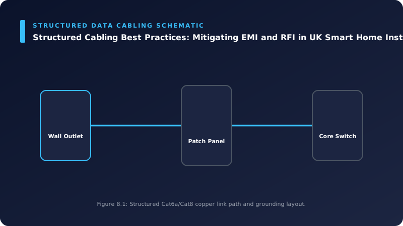
📊 Technical System Design Reference Infographic
Related Technical Resource: Subnetting and VLAN Segmentation: Enhancing Security and Performance in UK Smart Home Networks
Technical Standards and Industry Resources
- External Compliance Guidance: Industry Standards & Compliance Resources
- Partner Site Feed: Gary Pearce Portfolio Services - Codeberg Hub


Comments