Expert Guide to Cat7 Shielding Installations
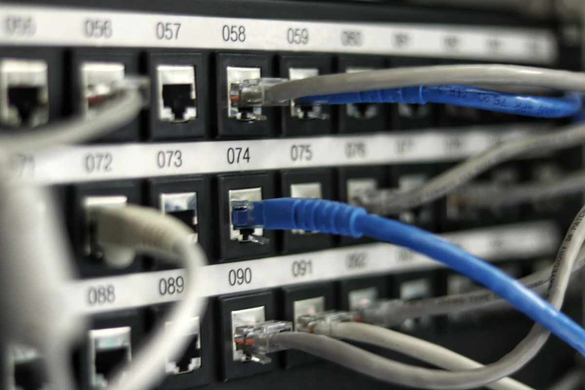
Expert Guide to Cat7 Shielding Installations: Ensuring Future-Proofed, High-Performance Networks
Greetings from Newcastle upon Tyne! As Gary Pearce, an NSI/SSAIB certified Security and Networking Engineer, I’ve spent decades designing, installing, and maintaining robust data and security infrastructure across the North East and beyond. In today's hyper-connected world, the demand for high-speed, reliable, and secure data transmission is non-negotiable. This is particularly true for sophisticated IP-based security systems, advanced building management solutions, and high-bandwidth multimedia applications.
While Cat5e and Cat6 cabling have served us well, the evolution of technology, especially with the proliferation of Power over Ethernet (PoE) devices and increasing data rates, necessitates a deeper understanding and often, the deployment of more advanced cabling solutions. That's where Category 7 (Cat7) shielding installations come into their own. This comprehensive guide will delve into the intricacies of Cat7, providing you with an expert-level understanding of its benefits, installation best practices, and crucial compliance considerations.
Understanding Data Cabling Categories: A Foundational Review
Before we dissect Cat7, it's essential to understand its lineage and how it stands apart from its predecessors and successors. Each category represents an advancement in performance, primarily concerning bandwidth (frequency) and data rates, alongside improved crosstalk mitigation.
Cat5e: A Foundation
Category 5 enhanced (Cat5e) cabling, specified up to 100 MHz, supports Gigabit Ethernet (1000BASE-T) over distances up to 100 metres. It’s unshielded (UTP) and remains common for basic networking, but its capabilities are increasingly strained by modern demands, particularly in environments with significant electromagnetic interference (EMI).
Cat6 and Cat6a: The Mainstays
Category 6 (Cat6) operates at up to 250 MHz and can support 10 Gigabit Ethernet (10GBASE-T) over shorter distances (up to 55 metres). Cat6a (augmented) extends this to full 100 metres at 500 MHz, making it a popular choice for many enterprise applications. Both Cat6 and Cat6a are commonly available as UTP, F/UTP (foil shielded around the overall bundle), or S/FTP (overall braid shield with foil shielded pairs). Their robust performance makes them excellent for general-purpose high-speed networking.
Cat7 and Cat7a: The Shielded Advantage
This is where our focus sharpens. Category 7 (Cat7) cabling, defined by ISO/IEC 11801 Class F, is engineered for extremely high-performance data transmission, operating at frequencies up to 600 MHz. Cat7a (augmented) pushes this even further to 1000 MHz. The defining characteristic of Cat7 and Cat7a is its comprehensive shielding. It typically employs an S/FTP (screened/foiled twisted pair) construction, meaning each individual wire pair is wrapped in its own foil shield, and then all four shielded pairs are encased in an overall braid shield.
This dual-layer shielding offers unparalleled immunity to alien crosstalk (AXT), near-end crosstalk (NEXT), and electromagnetic interference (EMI) or radio-frequency interference (RFI). While Cat7 can support 10 Gigabit Ethernet over its full 100-metre reach, its true value lies in its headroom for future applications and its superior signal integrity in challenging environments. It's often specified with GG45 or TERA connectors, which are backward compatible with RJ45 but designed to optimise performance at higher frequencies.
Cat8: The Next Frontier
For context, Category 8 (Cat8) is the latest standard, operating at frequencies up to 2000 MHz and designed to support 25 Gigabit Ethernet (25GBASE-T) and 40 Gigabit Ethernet (40GBASE-T) over short distances (up to 30 metres). Cat8 is exclusively shielded, often S/FTP, and uses specific Cat8.1 or Cat8.2 connectors. While truly bleeding-edge, for most commercial and industrial applications requiring robust 10GbE or high-capacity backbone, Cat7 offers a more practical and cost-effective solution with excellent future-proofing.
The Crucial Role of Shielding in Cat7 Installations
The "shielding" in Cat7 isn't just a buzzword; it's the core engineering principle that elevates its performance and reliability, especially in environments where signal integrity is paramount.
What is Shielding and Why Does it Matter?
Shielding in data cabling refers to the metallic barrier (typically foil or braid) surrounding the twisted wire pairs, or the entire cable bundle, to protect the internal data signals from external noise and to prevent internal signals from radiating outwards. This is a two-way street:
- EMI/RFI Reduction: External sources like fluorescent lighting, power cables, electric motors, radio transmitters, and even other data cables can emit electromagnetic interference. Shielding acts as a Faraday cage, attenuating these external noise sources before they can disrupt the delicate data signals within the cable.
- Alien Crosstalk (AXT) Prevention: In bundles of cables, signals from one cable can induce noise into adjacent cables. This "alien crosstalk" becomes particularly problematic at higher frequencies and longer distances. The individual foil shields around each pair in Cat7, combined with an overall braid shield, dramatically reduce AXT.
- Improved Signal Integrity: By minimising external interference and internal crosstalk, shielding ensures that the data signals maintain their intended strength and shape, leading to fewer errors, retransmissions, and ultimately, higher effective data throughput.
- Enhanced PoE Performance: With higher power levels transmitted over PoE (PoE, PoE+, PoE++), cables can experience significant heat generation. Shielding can help dissipate this heat more effectively, particularly in larger cable bundles, thus preserving the cable's transmission characteristics and longevity.
As mentioned, Cat7 predominantly utilises an S/FTP (Screened/Foiled Twisted Pair) construction. This means:
- Each of the four twisted pairs is individually wrapped in a foil shield (F/UTP). This provides excellent pair-to-pair isolation and crosstalk protection.
- All four individually shielded pairs are then encased in an overall braided shield (S/FTP). This offers robust protection against external EMI and AXT.
It is this multi-layered approach to shielding that provides Cat7 with its superior performance characteristics, making it ideal for environments where electromagnetic compatibility (EMC) is a concern or where maximum data reliability is required.
Planning and Design Considerations for Cat7 Installations
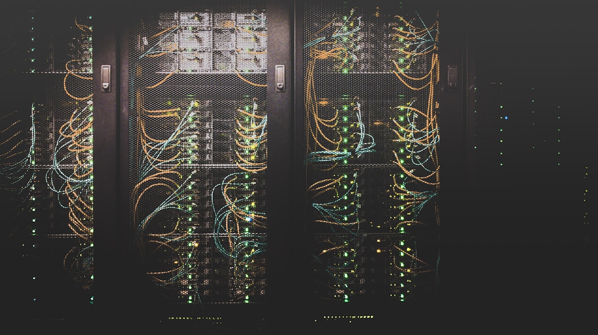
Figure 2: Quality installation standard deployment for Data Cabling.
A successful Cat7 installation begins long before any cable is pulled. Meticulous planning and design are critical to harness the full potential of this high-performance cabling.
Site Assessment and Cable Routing
Begin with a thorough site survey. Identify potential sources of EMI such as heavy machinery, power lines, fluorescent ballasts, and radio transmitters. Factor these into your cable routing strategy, aiming to maintain maximum separation from such sources. When separation isn't feasible, the robust shielding of Cat7 significantly mitigates the risk.
- Conduit Usage: Wherever possible, utilise dedicated conduits. This provides physical protection for the cable and can offer an additional layer of EMI shielding if metallic conduits are properly grounded.
- Bend Radius: Respect the cable's minimum bend radius. Over-bending Cat7 can deform the internal structure, compromise the shielding, and degrade performance. Manufacturers typically specify a minimum bend radius of 8 times the cable diameter during installation and 4 times the diameter for permanent routing.
- Cable Support: Ensure cables are adequately supported throughout their run, using appropriate cable trays, J-hooks, or ladder racks to prevent sagging and strain.
Power Over Ethernet (PoE) Budgets
The widespread adoption of PoE (IEEE 802.3af), PoE+ (802.3at), and the more powerful PoE++ (802.3bt Type 3 and Type 4) standards has transformed network design. These technologies deliver electrical power along with data over the same Ethernet cable to devices like IP cameras, wireless access points, VoIP phones, and IoT sensors. While incredibly convenient, the current flowing through the cable generates heat.
Higher power levels mean more heat. Cat7's larger conductor gauge (typically 22-23 AWG, compared to Cat5e/6's 23-24 AWG) helps reduce resistance and thus heat generation. Furthermore, its comprehensive shielding assists in heat dissipation, particularly in large cable bundles where temperatures can rise significantly. Proper cable management, allowing for adequate airflow, is also crucial to prevent heat-related performance degradation.
- Thermal Management: Account for heat rise in cable bundles, especially in conduits or enclosed spaces. Derate cable lengths if necessary, or opt for cables specifically designed for higher temperature applications.
- Power Requirements: Accurately calculate the power budget for all PoE-powered devices. Ensure your PoE switches or midspans can supply the necessary power and that the cabling can handle the current without excessive voltage drop or overheating.
Weatherproofing and External Deployments
For outdoor installations, such as connecting external CCTV cameras or wireless bridges, weatherproofing is paramount. Cat7 cables used outdoors must be rated for the environment. Look for jackets made from materials resistant to UV radiation, moisture, and extreme temperatures.
Beyond the cable itself, connections and enclosures demand attention:
- IP66/IP67 Rated Enclosures: All external terminations, patch panels, or device connections must be housed in enclosures with appropriate IP (Ingress Protection) ratings. IP66 protects against powerful water jets and dust ingress, while IP67 offers protection against temporary immersion in water.
- Sealed Connectors: Utilise outdoor-rated, sealed connectors (e.g., industrial RJ45 variants) that maintain the cable's weatherproofing and shielding integrity.
- Drip Loops: Implement drip loops for cables entering enclosures to prevent water from tracking along the cable into the housing.
- Grounding: External metallic components and cable shields must be properly grounded to prevent lightning damage and static discharge.
Security System Integration and Compliance
For an NSI/SSAIB certified engineer like myself, compliance is at the heart of every installation. When integrating Cat7 into security systems – particularly for CCTV, access control, or intruder alarms – the quality of the cabling directly impacts system reliability and regulatory compliance.
Cabling for security systems must adhere to standards such as EN 50131 (for intruder alarm systems), NSI (National Security Inspectorate), and SSAIB Inspectorate Board requirements. These standards dictate not only the performance but also the resilience and tamper-resistance of the infrastructure. Cat7's robust shielding is invaluable here, ensuring uninterrupted data flow for critical security sensors and cameras, free from electromagnetic interference that could cause false alarms or video dropouts.
Furthermore, the data transmitted by security systems, especially CCTV, often falls under stringent data protection regulations. Understanding how to manage this data is crucial. I've previously outlined these considerations in A Guide to GDPR Compliance for Domestic CCTV Systems Facing Public Highways, which highlights the broader compliance landscape.
For Grade 2 and Grade 3 security installations (EN 50131), the cabling itself is a critical component of the system's integrity. Ensuring proper shielding and termination means the system is less susceptible to external attacks or environmental interference, which could compromise its security rating.
Detailed Installation Procedures for Cat7 Shielded Cabling
The superior performance of Cat7 is only realised through meticulous installation. Shortcuts in handling or termination can negate the benefits of its advanced design.
Tools and Equipment Required
For a professional Cat7 installation, you’ll need a specific toolkit:
- High-quality cable pulling lubricant (non-damaging to cable jacket).
- Cable strippers designed for Cat7 (to precisely cut outer jacket without nicking shields or conductors).
- Specialised termination tools for GG45 or TERA connectors/modules. These are different from standard RJ45 crimpers.
- Cable tie gun (to ensure consistent tension).
- Permanent markers and cable labels for clear identification.
- Continuity tester and, critically, a certified cable analyser (e.g., Fluke Networks Versiv DSX series) for testing and certification.
- Grounding/bonding equipment: grounding bars, earth straps, and associated fasteners.
Cable Handling and Pulling Techniques
The integrity of Cat7's shielding is fragile if mishandled. Adhere to these principles:
- Avoid Kinks and Twists: Never allow the cable to kink or twist sharply. This can damage the internal structure, compromise the twisted pairs, and break the foil shields.
- Respect Bend Radius: As discussed, strictly observe the manufacturer's specified minimum bend radius during installation and permanent routing. Use large sweeps around corners.
- Control Pulling Tension: Excessive pulling tension can stretch the cable, altering its electrical characteristics and damaging the shielding. Use a tension-controlled pulling device or multiple pull points for long runs. The maximum pulling tension for copper cables is typically 110 N (25 lbf).
- Lubrication: For longer runs or pulls through conduits, use a suitable cable lubricant to reduce friction and pulling tension.
- Cable Management: Route cables neatly, separating power and data where possible to minimise residual EMI. Use hook-and-loop fasteners instead of tight plastic cable ties to prevent crushing the cable and deforming its geometry, which can lead to performance issues.
Termination Techniques: GG45/TERA Connectors
This is arguably the most critical step for Cat7. Unlike standard RJ45, Cat7 often uses GG45 (GigaGate 45) or TERA connectors, designed to maintain performance at frequencies up to 600/1000 MHz. While some Cat7 cables are sold with RJ45 compatible connectors, true Cat7 performance often requires the specialised connectors.
General Steps for GG45/TERA Termination (e.g., for a patch panel module):
- Prepare the Cable: Carefully strip the outer jacket to the length recommended by the connector manufacturer. Be precise; avoid nicking the overall braid shield or the internal foil shields.
- Expose Overall Braid Shield: Gently push back the overall braid shield. Ensure it remains intact and can be securely terminated to the connector's ground point.
- Expose Individual Foil Shields: Carefully unwrap or remove the individual foil shields from each twisted pair. Some GG45/TERA systems require these foils to be folded back to maintain shield continuity to the connector.
- Untwist Pairs: Minimally untwist the pairs. The less untwisting, the better for maintaining performance.
- Arrange Conductors: Arrange the conductors according to the wiring scheme (T568A or T568B). The GG45/TERA connector will have a specific guide or colour code.
- Insert and Terminate: Insert the conductors into the connector/module. Use the specialised termination tool to punch down or crimp the conductors and simultaneously trim any excess. Ensure a solid, gas-tight connection.
- Ground the Shield: Critically, ensure the overall braid shield, and where applicable, the individual foil shields, are properly bonded to the metal housing of the GG45/TERA connector or patch panel module. This connection is vital for dissipating EMI and maintaining shield continuity.
- Secure and Inspect: Secure any cable strain relief. Visually inspect the termination for any stray wires, damaged insulation, or inadequate shield connection.
Key Shielding Principle: For S/FTP cables like Cat7, the *overall* braid shield should ideally be grounded at one end only in a building to prevent ground loops, typically at the patch panel in the equipment room. However, the *individual* foil shields around each pair and the overall shield *must* maintain continuity throughout the cable run and through all connections to the end device to be effective. This is a crucial distinction from unshielded cabling.
Grounding and Bonding Best Practises
Effective grounding is non-negotiable for shielded cabling. Improper grounding can turn your shield into an antenna, attracting noise rather than dissipating it, or even create dangerous ground loops.
- Single-Point Grounding: For horizontal runs, the general best practice is to ground the overall cable shield at one end only, typically at the patch panel in the telecommunications room. This helps prevent ground loops. However, devices at the far end (e.g., an IP camera) should also have their local chassis properly bonded to the nearest building ground.
- Equipotential Bonding: Ensure all metallic components of the cabling system (racks, patch panels, conduits, equipment enclosures) are bonded together to form an equipotential plane and then connected to the building's main earthing terminal. This minimises potential differences and ensures any induced currents are safely directed to ground.
- Dedicated Earth: Where possible, utilise a clean, dedicated earth connection for IT and security infrastructure to avoid noise from general electrical systems.
- Avoid Ground Loops: A ground loop occurs when there are multiple paths to ground, leading to current flow between them, which can induce noise. Proper single-point grounding helps mitigate this.
Verification, Testing, and Troubleshooting
Installation isn't complete until the cable is thoroughly tested and certified. This step validates the quality of your work and ensures the network will perform as expected.
Certification Testing with Cable Analysers
For Cat7, a basic continuity tester is insufficient. You require a high-frequency cable analyser (e.g., from Fluke Networks, Viavi, or Softing) capable of certifying to ISO/IEC Class F or Class Fa standards. The analyser will perform a suite of tests:
- Wire Map: Confirms correct pin-to-pin wiring, detecting opens, shorts, crossed pairs, split pairs, and reversed pairs.
- Length: Measures the physical length of each pair and the overall cable.
- Insertion Loss (Attenuation): Measures signal loss along the cable. High loss indicates excessive length, poor connections, or damage.
- Return Loss: Measures signal reflections caused by impedance mismatches. High return loss often points to kinks, tight bends, or poor terminations.
- Near-End Crosstalk (NEXT) & Power Sum NEXT (PSNEXT): Measures interference between pairs within the same cable at the near end.
- Far-End Crosstalk (FEXT), Equal-Level FEXT (ELFEXT), & Power Sum ELFEXT (PSELFEXT): Measures interference between pairs at the far end.
- Alien Crosstalk (AXT) & Power Sum Alien Crosstalk (PSAXT): Crucially for shielded cables, this measures interference between adjacent cables in a bundle. Cat7's design dramatically reduces this.
- Delay Skew: Measures the difference in propagation time between the fastest and slowest pairs. Important for high-speed data.
- Propagation Delay: Measures the time it takes for a signal to travel from one end of the cable to the other.
Successful certification provides a robust report, essential for warranty claims, client acceptance, and future troubleshooting. It's the definitive proof that your Cat7 installation meets or exceeds industry standards.
Common Issues and Troubleshooting
Even with careful installation, issues can arise. A systematic approach to troubleshooting is key:
- No Link/Intermittent Link:
- Wire Map Errors: The most common culprit. Re-examine terminations for opens, shorts, or miswired pairs.
- Damaged Connectors: Bent pins, poor seating.
- Incorrect Drivers/Settings: Check network interface card (NIC) drivers and speed/duplex settings.
- Slow Performance/High Error Rates:
- High Insertion Loss: Cable length exceeds maximum, poor crimps, damaged cable, or incorrect cable type for application.
- High Return Loss: Kinks, tight bends, improper impedance matching, or poor quality connectors.
- High NEXT/AXT: Poor terminations, excessive untwisting of pairs, damaged shielding, or running parallel to EMI sources without proper separation/grounding.
- Grounding Problems: Inadequate shield termination or presence of ground loops can cause the shield to act as an antenna, picking up noise instead of rejecting it.
- PoE Issues:
- Insufficient Power: PoE budget exceeded, faulty PoE injector/switch port.
- Voltage Drop: Excessive cable length, undersized conductors, or poor connections causing resistance.
- Overheating: Cables bundled too tightly in hot environments, leading to increased resistance and performance degradation. Check cable jacket for signs of stress or melting.
- Environmental Interference:
- If the cable passes certification but performance issues persist, investigate external EMI/RFI sources. Check grounding system thoroughly. Consider rerouting or adding additional metallic shielding (e.g., inside conduit) if the source cannot be eliminated.
Always start troubleshooting with the simplest checks (visual inspection, basic connectivity) and then move to advanced diagnostics with the cable analyser. Document all findings and corrective actions.
| Parameter | Cat5e | Cat6 | Cat6a | Cat7 | Cat8 |
|---|---|---|---|---|---|
| Max Frequency | 100 MHz | 250 MHz | 500 MHz | 600 MHz (Cat7a: 1000 MHz) | 2000 MHz |
| Max Speed (100m) | 1 Gbps | 1 Gbps (10 Gbps up to 55m) | 10 Gbps | 10 Gbps | 25/40 Gbps (up to 30m) |
| Shielding Type (Common) | UTP (Unshielded) | UTP, F/UTP, S/FTP | UTP, F/UTP, S/FTP | S/FTP (Ind. Foil Pairs + Overall Braid) | S/FTP or F/FTP (Always Shielded) |
| Connector Type | RJ45 | RJ45 | RJ45 | GG45, TERA (RJ45 Compatible) | Cat8.1 (RJ45), Cat8.2 (GG45/TERA) |
| ISO/IEC Classification | Class D | Class E | Class Ea | Class F (Cat7a: Class Fa) | Class I, Class II |
| Typical Use Cases | Basic networking, VoIP, older IP cameras | Gigabit Ethernet, small business, residential | 10 Gigabit Ethernet, enterprise backbone, data centre access | 10 Gigabit Ethernet, high EMI environments, AV over IP, future-proofing | 25/40 Gigabit Ethernet (short runs), data centre interconnect |
Conclusion
The decision to utilise Cat7 shielding in your data cabling infrastructure is a strategic one, offering unparalleled performance, resilience against interference, and robust future-proofing for your network. As an NSI/SSAIB certified engineer, I've seen firsthand how properly installed Cat7 can elevate the reliability of critical systems, from high-definition surveillance networks to complex building automation platforms.
From meticulous planning and understanding PoE budgets to executing precise termination techniques and rigorous certification testing, every stage of a Cat7 installation demands expert attention. By adhering to the detailed guidelines outlined in this guide – encompassing cabling standards, power considerations, weatherproofing, and vital security compliance – you can ensure your Cat7 deployment not only meets but exceeds the exacting demands of today's, and tomorrow's, digital landscape.
Invest in professional installation, and you invest in the long-term integrity and performance of your core infrastructure. Get it right, and your network will serve you reliably for years to come.
Q: What details do you provide regarding How to Repair and Maintain Plenum-Rated Cabling?
A: We have written an extensive guide on this. Read our complete guide to How to Repair and Maintain Plenum-Rated Cabling or contact Gary Pearce on 07830638337.
Q: What details do you provide regarding Step-by-Step Backbone Infrastructure Configuration Guide?
A: We have written an extensive guide on this. Read our complete guide to Step-by-Step Backbone Infrastructure Configuration Guide or contact Gary Pearce on 07830638337.
Q: What details do you provide regarding Comparing Attenuation Mitigation Options for Modern Homes?
A: We have written an extensive guide on this. Read our complete guide to Comparing Attenuation Mitigation Options for Modern Homes or contact Gary Pearce on 07830638337.
Q: What details do you provide regarding Expert Guide to Underfloor Cable Trays Installations?
A: We have written an extensive guide on this. Read our complete guide to Expert Guide to Underfloor Cable Trays Installations or contact Gary Pearce on 07830638337.
? Frequently Asked Questions
Q: What details do you provide regarding Improving Performance of your Fiber Optic Fusion Splicing?
A: We have written an extensive guide on this. Read our complete guide to Improving Performance of your Fiber Optic Fusion Splicing or contact Gary Pearce on 07830638337.
Q: What details do you provide regarding How to Repair and Maintain Plenum-Rated Cabling?
A: We have written an extensive guide on this. Read our complete guide to How to Repair and Maintain Plenum-Rated Cabling or contact Gary Pearce on 07830638337.
Q: What details do you provide regarding Step-by-Step Backbone Infrastructure Configuration Guide?
A: We have written an extensive guide on this. Read our complete guide to Step-by-Step Backbone Infrastructure Configuration Guide or contact Gary Pearce on 07830638337.
Q: What details do you provide regarding Comparing Attenuation Mitigation Options for Modern Homes?
A: We have written an extensive guide on this. Read our complete guide to Comparing Attenuation Mitigation Options for Modern Homes or contact Gary Pearce on 07830638337.
Q: What details do you provide regarding Expert Guide to Underfloor Cable Trays Installations?
A: We have written an extensive guide on this. Read our complete guide to Expert Guide to Underfloor Cable Trays Installations or contact Gary Pearce on 07830638337.
Need a Professional Quote?
Trust Gary Pearce Home Services for NSI and SSAIB certified installations. Expert, reliable, and compliant.


Comments