Common Mistakes to Avoid in Junction Box Splicing setups in Prudhoe

An Expert Engineer's Guide to Correct Cable Repair and Splicing Standards
As an NSI and SSAIB certified Security and Networking Engineer based in Newcastle upon Tyne, I frequently travel along the Tyne Valley to assist residential and commercial clients in Prudhoe. Whether addressing network drops in a converted stone property near Prudhoe Castle or correcting faults in a commercial unit on the Low Prudhoe Industrial Estate, I encounter one issue more than almost any other: poorly executed cable repairs and incorrect junction box splicing.
In high-speed data transmission and high-reliability IP security systems, a single poorly terminated junction box can compromise an entire system. It introduces return loss, impedance mismatches, high resistance, and vulnerability to environmental moisture. This comprehensive guide outlines the critical technical mistakes engineers and system integrators must avoid when executing junction box splicing configurations in Prudhoe and the wider Northumberland region.
When dealing with high-frequency signalling such as Category 6 (Cat6) or Category 6A (Cat6A), physical copper repairs are not as simple as twisting wires together and wrapping them in electrical tape. They require careful consideration of electrical theory, signal attenuation, mechanical stress, and strict adherence to British and European standards.
1. Disregarding Cabling Standards and Category Geometry
The first and most pervasive mistake is failing to match the mechanical splicing method to the specific category standard of the network cable (Cat5e, Cat6, Cat6A, Cat7, or Cat8). Every Ethernet cable category is designed to strict physical geometries that dictate bandwidth capabilities and noise resistance:
- Category 5e (Cat5e): Operates at frequencies up to 100 MHz. It has looser twist rates and is more forgiving, but still requires tight terminations to prevent Near-End Crosstalk (NEXT).
- Category 6 (Cat6): Operates at frequencies up to 250 MHz. It features tighter twists and often includes a physical internal spline (separator) to isolate the pairs. Splicing must maintain these twists up to the point of termination.
- Category 6A (Cat6A): Designed for 10 Gigabit speeds at 500 MHz. These cables feature robust shielding (F/UTP or S/FTP) to eliminate alien crosstalk. Breaking the shield continuity during a repair completely invalidates its high-frequency performance.
- Category 7 & 8 (Cat7/Cat8): Built for ultra-high-frequency applications (up to 600 MHz and 2000 MHz respectively). These cables require specialist metal-clad, fully shielded junction boxes. General-purpose punch-down blocks are completely unsuitable.
When performing a repair, many technicians untwist the internal copper pairs far too much. For Cat6 and Cat6A cables, standard regulations specify that the pair twist must be maintained within 13mm (0.5 inches) of the termination point. Stripping back the jacket by several inches and leaving untwisted leads exposed inside a junction box creates an impedance mismatch. This reflects high-frequency signals back to the source, resulting in packet loss, reduced throughput, and random connection drops.
Furthermore, using non-category-rated terminal blocks or cheap chocolate-block connectors on a Cat6A line destroys its electrical characteristics, reducing its performance to below Cat3 standards. If you are dealing with a complex domestic installation, the temptation to use quick-fix connectors can be incredibly high. For home occupiers in Northumberland, understanding these physical limitations is key. Our internal guide, Assessing the Risks of DIY Smart Home Network Configurations, details how sub-standard terminations can quickly compromise local network stability.
2. Overlooking Power over Ethernet (PoE) Budgets and Resistance Spikes
Modern networks do not just carry data; they carry power. IP security cameras, access control doors, and wireless access points across Prudhoe rely on Power over Ethernet (PoE, PoE+, and PoE++). Splicing network cables significantly alters the DC resistance of the transmission line, which can have dangerous consequences for your power budget and system stability.
Under IEEE standards, PoE delivers power across several classes:
- PoE (IEEE 802.3af): Delivers up to 15.4W of DC power per port.
- PoE+ (IEEE 802.3at): Delivers up to 30W of DC power per port.
- PoE++ (IEEE 802.3bt Type 3 & 4): Delivers up to 60W or 90W of DC power per port, utilizing all four pairs of the copper cable.
Every mechanical connection in a cable run introduces contact resistance. If a technician uses poor-quality junction boxes, loose screw terminals, or cheap insulation displacement connectors (IDCs), the local resistance at the splice point increases significantly. This causes two primary failures:
Voltage Drop and Port Disconnects
As current flows through a high-resistance splice, a voltage drop occurs across the junction according to Ohm’s Law ($V = I \times R$). By the time the power reaches an active PTZ (Pan-Tilt-Zoom) camera on an external wall, the voltage may have dropped below the camera’s minimum operating threshold. This causes the camera to reboot whenever it draws peak power (e.g., when the infrared LEDs turn on or the PTZ motor engages).
Thermal Dissipation and Fire Hazards
Power dissipated as heat at a high-resistance joint is calculated as $P = I^2 \times R$. When running high-power PoE++ (up to 960mA per pair), even a minor resistance spike of 2 to 3 Ohms can generate localized heating inside a plastic junction box. Over time, this thermal stress degrades the conductor insulation, causes plastic brittleness, and poses a genuine fire hazard.
Furthermore, utilizing Copper Clad Aluminium (CCA) cable rather than Solid Bare Copper (SBC) is a major issue in DIY setups. CCA wire has high DC resistance, is extremely brittle, and breaks easily when punched down into standard IDC Krone slots. Combining CCA with a low-grade junction box under PoE load is a recipe for system failure.
3. Ignoring Environmental Protection and Weatherproofing (IP66 vs IP67)
Prudhoe is situated along the River Tyne, making it susceptible to cold wind, high humidity, driving rain, and dense winter frosts. Installing a standard indoor-rated junction box on an external wall, in an unheated loft space, or inside a damp underground chamber will lead to rapid oxidisation of the copper conductors.
When selecting outdoor enclosures for cable repairs, engineers must understand Ingress Protection (IP) ratings and select the correct standard for the environmental hazards:
Common failures I see during inspections include using an IP66 enclosure but failing to tighten the compression glands around the entry cables. If a gland is too loose, or if multiple cables are fed through a single gland, moisture will bypass the seal via capillary action. Warm air inside the junction box cools down rapidly at night, drawing damp air in. This moisture condenses on the cold copper connections, causing corrosion (green copper carbonate buildup) and short circuits.
To prevent this, external splices must feature downward-facing cable entry points with integrated drip loops. These loops force rainwater to pool and drop off the cable sheath before reaching the entry gland. In highly exposed or below-ground environments, the entire junction box should be backfilled with a self-curing, semi-flexible, two-part polyurethane re-enterable gel. This gel encases the terminations, preventing moisture contact even if the outer enclosure is submerged.
4. Disregard for Security System Compliance (NSI, SSAIB, & EN 50131)
For systems handling security-critical infrastructure, such as intruder alarms, access control systems, and CCTV, repair methods are strictly governed. They must comply with regional and national insurance-approved bodies like the Security Systems and Alarms Inspection Board (SSAIB) and the National Security Inspectorate (NSI).
If a cable splice forms part of an intruder alarm system, it must comply with BS EN 50131 standards. These regulations classify systems into security grades:
- Grade 1 (Low Risk): Basic residential systems where intruders are expected to have minimal knowledge of security installations.
- Grade 2 (Medium Risk): Standard residential and light commercial properties. These systems must resist tampering from opportunist intruders with basic tools.
- Grade 3 (High Risk): Commercial and industrial sites. Systems must withstand sophisticated attempts to bypass or sabotage sensors, cabling, and communication links.
Under Grade 2 and Grade 3 standards, any junction box used to splice security cabling must incorporate active tamper detection mechanisms. If an intruder attempts to unscrew the cover of a junction box to bypass a magnetic door contact or PIR sensor, a spring-loaded microswitch must open, immediately triggering a system-wide tamper alarm. Using standard electrical junction boxes or plastic project boxes on a security circuit instantly invalidates its NSI/SSAIB compliance, which can void the building's insurance policy.
Furthermore, critical CCTV cameras deployed for public safety or business security must comply with data privacy and operational standards set by the Information Commissioner's Office (ICO). If an unshielded, non-waterproofed splice fails intermittently, it can lead to missing footage during a security incident. This failure to maintain a continuously operating system can lead to compliance issues for local businesses during audit procedures.
5. Correct Splicing Methodology: Installation & Testing Procedures
To ensure a reliable splice that preserves category ratings, maintains PoE budgets, and complies with safety standards, engineers must follow a precise installation process.
Step 1: Selecting the Correct Connector
Never use crimp-on RJ45 plugs with a female-to-female coupler for permanent inline repairs. Couplers add two extra contact points, doubling the signal loss. Instead, use a dedicated, metallic-shielded IDC (Insulation Displacement Contact) Inline Splice Junction Box specifically rated for your cable category (e.g., a Cat6 LSA-Plus punch-down module).
Step 2: Preparing the Cable
Carefully remove no more than 25mm of the outer PVC or LSZH jacket. Do not use standard wire strippers or utility knives that can nick the copper conductors. Instead, use a specialized rotary sheath cutter. If the cable is shielded (F/UTP), preserve the foil shield and ensure the drain wire remains intact.
Step 3: Maintaining Geometric Integrity
Thread the individual conductors into the junction box’s routing channels while keeping the pair twists intact. Only untwist the absolute minimum required to seat the wires into the IDC terminals. If you are using a shielded box, ensure the cable’s drain wire is wrapped securely around the metal grounding clamp of the enclosure to maintain ground continuity across the entire run.
Step 4: Executing the Punch Down
Use a professional, calibrated Krone or 110 Punch-Down Tool with a clean cutting blade. Do not use flat-head screwdrivers or pliers, which can damage the IDC V-shaped slots. The tool must slide the copper wire firmly into the terminal, slicing through the plastic insulation to form a cold-welded, gas-tight bond, while simultaneously shearing off the excess copper tail in one clean movement.
Step 5: Environmental Sealing
If installing outside, insert the assembly into an IP66 or IP67 enclosure. Tighten the compression glands with a spanner to ensure a secure seal on the cable jacket. If the run is in a high-humidity environment or an underground chamber, fill the enclosure with a non-conductive, re-enterable potting compound.
6. Troubleshooting and Verification Testing
Once a cable has been spliced, it must be thoroughly tested. Simply plugging in a basic £10 continuity tester is not sufficient. These budget testers only check for pin-to-pin continuity; they do not measure frequency, return loss, crosstalk, or impedance.
To verify that a repaired run meets industry standards, professional engineers use a certified cable analyzer, such as a Fluke DSX series tester. This advanced equipment runs a suite of tests to verify performance up to the cable's maximum category frequency:
- Time Domain Reflectometry (TDR): This test sends electrical pulses down the cable to measure its impedance characteristics. If there is a poor-quality splice, the TDR detects the exact distance to the fault, allowing the engineer to locate the failing junction box.
- Return Loss: Measures the amount of signal reflected back toward the transmitter. High return loss at a splice indicates a poorly maintained pair geometry or an improper connector choice.
- Near-End Crosstalk (NEXT): Measures signal leakage between adjacent pairs inside the cable. Excessive untwisting of pairs at the splice point causes NEXT values to spike, which can lead to packet transmission failures.
- Shield Integrity Test: Verifies that the grounding path remains continuous across the repair point. If the shield is broken or not properly connected to the chassis, the cable becomes highly susceptible to electromagnetic interference (EMI) from nearby mains power cables.
By avoiding these common mistakes and adhering to proper category specifications, environmental protection measures, and NSI/SSAIB security guidelines, you can ensure your network and security infrastructure in Prudhoe remains reliable, secure, and compliant for years to come.
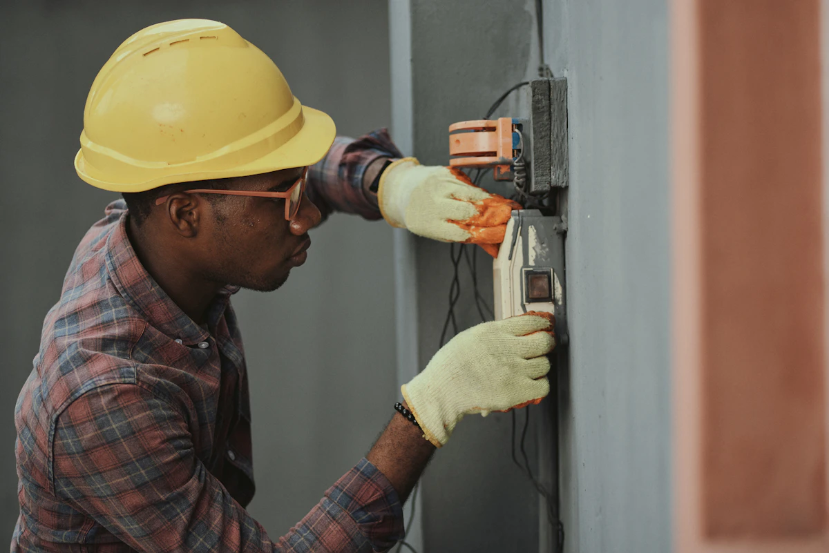
Figure 2: Quality installation standard deployment for Cable Repairs.
? Frequently Asked Questions
Q: What details do you provide regarding Common Mistakes to Avoid in Ethernet Cable Splicing setups in Amble?
A: We have written an extensive guide on this. Read our complete guide to Common Mistakes to Avoid in Ethernet Cable Splicing setups in Amble or contact Gary Pearce on 07830638337.
Q: What details do you provide regarding Common Mistakes to Avoid in Water Ingress Cable Corruption setups in Sunderland?
A: We have written an extensive guide on this. Read our complete guide to Common Mistakes to Avoid in Water Ingress Cable Corruption setups in Sunderland or contact Gary Pearce on 07830638337.
Q: What details do you provide regarding Common Mistakes to Avoid in Junction Box Splicing setups in Gateshead?
A: We have written an extensive guide on this. Read our complete guide to Common Mistakes to Avoid in Junction Box Splicing setups in Gateshead or contact Gary Pearce on 07830638337.
Q: What details do you provide regarding Common Mistakes to Avoid in Ethernet Cable Splicing setups in Hartlepool?
A: We have written an extensive guide on this. Read our complete guide to Common Mistakes to Avoid in Ethernet Cable Splicing setups in Hartlepool or contact Gary Pearce on 07830638337.
Q: What details do you provide regarding Common Mistakes to Avoid in Water Ingress Cable Corruption setups in Blyth?
A: We have written an extensive guide on this. Read our complete guide to Common Mistakes to Avoid in Water Ingress Cable Corruption setups in Blyth or contact Gary Pearce on 07830638337.
Need a Professional Quote?
Trust Gary Pearce Home Services for NSI and SSAIB certified installations. Expert, reliable, and compliant.
Comments
Post a Comment